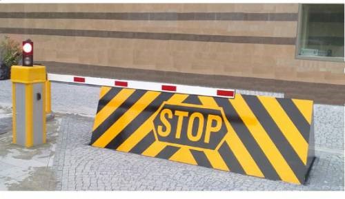
RISING ROAD BLOCKER TECHNICAL SPECIFICATIONS
Rising Road Blocker; is used for vehicle passing in areas that requries higher security. Rising Road Blocker; restricts vehicles up to 15 tones per axle and when brought down to groundit will not restrict the vehicle’s passing and vehicles will not be
damaged. Rising Road Blocker Dimensions can be manufactured according to the administrative contract which will requried. Standard dimensions are 1000x3000x800 mm – 1000x4000x800 mm – 1000x5000x800 mm. The part of Road Blocker which
will be remain under the ground is manufactured by 120 NPU nominal diameter, intermediate pillar’s nominal diameter is strenghened with 100 NPI and painted with satatic paint over hot deep galvanization. A hole is formed with dimensions
of Anchorage part of the Road Blockerand after leaving a space for connection cables, power unit, and evacuation space for the drain water and steam that will arise in space that moving part forms, it will be concreted with minimum
C35 concrete and waited for 1 week period. It can vary upon weather and climate conditions of the region. After manufacturing the nominal diameter for the case of the moving barrier part of Road Blocker by 120 NPU, the upper
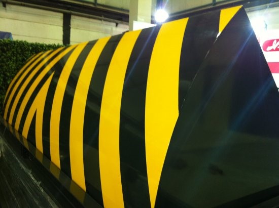
part (the part that wheels of vehicle touches) will be coreved with 10mm ST 37 quality sheet iron and after galvanization of it will be painted wtih static paint having the same colour as level crossing. Corrosion is prevented by hinging
anchorage and moving barrier part of Road Blocker from 5 points and being anchoraged with yellow brass that is cut with laser and processed in lathe. Road Blocker; by its shock ansorbing features, internal mechanical parts are prevented
for crashes that are coming from front. The front and side covers of Road Blocker is processed modularly with 3mm ST37 iron sheet ant painted with static paint over hot deep galvanization. The hydraulic piston and moving barrier part
of Road Blocker are prevented for crashes and shocks by using 20 mm chains. The security of the Road Blocker is established by metal perception loop sensors and infrared sensors. After installation of Road Blocker, Operating Training
will be given to minimum 5 people which will be determined by the adminitration.
SPECIFICATIONS
| OPERATING : | 220V 50-60HZ , 380V 50-60HZ |
| OPERATING TEMP : | -25 C +60 C |
| DURABILITY | 130 C |
| CURRENT USED : | 1.2 A (For 230V), 6A (For 380V) |
| ON / OFF CAPASITY : | 1000 PER DAY |
| IP STANDARD : | IP67 |
| VALVE : | Double way 220V Celonoide |
| PISTON : | 50X500X25 Lift |
| H.COMPRESSOOR : | 90 Bar Hydrolic |
| HOSEPIPE : | 250 Bar durability |
| MANUEL WORK : | Manuel Pump |
| TOP COVER : | Fit with Level corssing Way |
| COATING : | Hot Deep Galvanized |
| H.UNIT COVER : | Elecrostatic Polyester |
BODY STRUCTURE
| IMPACT DURABILITY : | %50 Breaking Probability against an impact of 500mm heightand 150000 J |
| WEIGHT : | 1100 – 1300 kg ROAD BLOCKER – BOLLARDS 80 kg |
| CONTROL PANEL : | Microprocessor or PLC Relay control |
OPTIONAL ACCESSORY
| REISTANT HEATHER : | Internal Heather |
| FLASHER : | Sun Panelon top cover |
| WARNING SIGNALS : | Traffic light (red,green) |
BOLLARDS
PNEUMATIC and HYDRAULIC MUSHROOM BARRIER BOLLARDS (SAFETY FENCES) TECHNICAL CONTRACT
Type Bollards
Subject
This technical contract is including technical specifications for KYSP Automation Systems Pneumatic and Hydraulic Mushroom Barriers
AUTOMATION TECHNICAL SPECIFICATIONS
| ENGINE | 220V 50-60HZ 1500 d/d 1.5 KW PNEUMATIC |
| ENGINE | 380V 50-60HZ 1500 d/d 2.5 KW HYDRAULIC |
| OPERATING TEMPERATURE | – 25 +60 C |
| TEMPERATURE DURABILITY | 130 C |
| IP STANDARD | IP 67 |
| ON/OFF CAPACITY | 1000 CYCLE/DAY |
| ON/OFF PERIOD | 4 – 10 SECONDS OPTIONAL |
| CRASH DURABILITY | 2 TONES 80 KM VELOCITY % 50BREAKING PROBABILITY |
| FREEZING PREVENTION | 220 V HEATER TERMOSTATIC KIT |
| WARNING | WARNING SIGNBOARD TRAFFIC LAMB FLASHER(OPTIONAL) |
| GROS WEIGHT | 80 KG |
| AUTOMATION CONTROL | MICRO PROCESSOR- P.L.C. SMART RELAY LOGIC SOFTWARE |
| SAFETY | INFRARED SENSORS- METAL MASS DEDECTOR LOOP |
| AUTOMATION DIRECTING | 220V DOUBLE SIDED SELENOID VALVE |
AYKARMAK Machine İmagination Manufactured İndustry Company. Adnan Kahveci Mah. Bülent Ecevit Cad. No 14/3 Beylikdüzü/İstanbul
Tlf: +90 212 509 5851
Fax: +90 212 509 5155
GSM: +90 532 662 6027
E.Mail:
info@aykarmak.com
General Definition and Mechanical Specifications
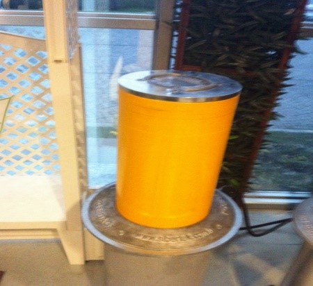
Mushroom barriers are used in places that requires higher security, in conditions that requires controlled entrance and exit of vehicles, in places that vehicle passing is not authorized.
Mushroom barrier’s case dimensions are 263x5x700 mm and will be manufactured by ST 37 steel. And inside and outside of the case will be covered by galvanization.
The bearing part will be manufactured by 217x10x200 mm 912 quality steel. Honing will be applied and will be grinded and inside and outside of it will be covered by chrome.
The bearing part of the barrier will be grinded by 2 pieces of polyamide 30×2,5 mm polyamide circles.
Moving cylinder of mushroom barrier will be manufactured by 195x10x700 mm diameter 912 quality complied steel, honing will be applied, grinded and outside will be covered by 50 micron chrome. Inside will be painted with static paint.(RAL 9006).
Over the moving cylinder of mushroom barrier 215×40 mm polyamide cover will be put. Polyamide cover will be fixed to moving cylinder with 2 pieces of stainless screw.
Inside of Polyamide cover of Mushroom barrier red leds will be located in a place that can be seen from all angles and if required flashes can be put.
2365×1 0x50 mm flansh assembled electro galvanized dust seal which is made of ST steel will be used on floor part of mushroom barrier that is touching asphalt or concrete.
Pneumatic piston ISO 6431 VDMA 80-500
Selenoid valve brand: metal Work “-220VAC details are specified in the appendix.
Pneumatic hosepipes brand: Metal Work 6,5×10 mm 20 Bar polyurethane hosepipe.
Connector Brand: metal work 10 mm male straight connector.